הצהרת פרטיות: הפרטיות שלך חשובה לנו מאוד. החברה שלנו מבטיחה לא לחשוף את המידע האישי שלך לכל אקסני עם ההרשאות המפורשות שלך.
מספר דגם.: NSO4GU3AB
הוֹבָלָה: Ocean,Air,Express,Land
סוג תשלום: L/C,T/T,D/A
Incoterm: FOB,EXW,CIF
4GB 1600MHz 240 פינים DDR3 UDIMM
היסטוריה של עדכון
|
Revision No. |
History |
Draft Date |
Remark |
|
1.0 |
Initial Release |
Apr. 2022 |
|
![]()
טבלת מידע על הזמנה
|
Model |
Density |
Speed |
Organization |
Component Composition |
|
NS04GU3AB |
4GB |
1600MHz |
512Mx64bit |
DDR3 256Mx8 *16 |
תיאור
Hengstar DDR3 SDRAM DIMMs ללא דרישה (קצב נתונים כפול לא מפוצץ, מודולי זיכרון כפולים כפולים בשורה כפולה) הם מודולי זיכרון עם הפעלה במהירות גבוהה המשתמשות במכשירי SDRAM DDR3. NS04GU3AB הוא 512 מ 'x 64 סיביות שני דרגות 4 ג'יגה-בייט DDR3-1600 CL11 1.5V SDRAM מוצר DIMM ללא פגיעה, מבוסס על רכיבי FBGA של שישה עשר 256 מ' x 8 סיביות. ה- SPD מתוכנת לתזמון ה- DDR3-1600 הסטנדרטי של JEDEC Standard DDR3-1600 של 11-11-11 ב 1.5 וולט. כל DIMM בן 240 פינים משתמש באצבעות מגע זהב. DIMM של SDRAM Unfuffed מיועד לשימוש כזיכרון ראשי כאשר הוא מותקן במערכות כמו מחשבים אישיים ותחנות עבודה.
מאפיינים
Supply אספקת כוח: VDD = 1.5V (1.425V עד 1.575V)
VDDQ = 1.5V (1.425V עד 1.575V)
800MHz FCK עבור 1600MB/SEC/PIN
8 בנק פנימי עצמאי
השהיית CAS המתוכננת: 11, 10, 9, 8, 7, 6
חביון תוסף לתכנות: 0, Cl - 2 או Cl - שעון 1
8 סיביות קדם-פץ '
אורך התפרצות: 8 (זה בזה ללא גבול, ברצף עם כתובת ההתחלה "000" בלבד), 4 עם TCCD = 4 שאינו מאפשר קריאה או כותבים חלקים [בזבוב באמצעות A12 או MRS]
Strobe Differential Differential Strobe
Cullation כיול פנימי (עצמי); כיול עצמי פנימי דרך סיכת ZQ (RZQ: 240 אוהם ± 1%)
סיום הפסקות באמצעות סיכת ODT
תקופת רענון ממוצעת 7.8US בתשנית נמוכה מ- TCASE 85 מעלות צלזיוס, 3.9US ב 85 מעלות צלזיוס <tcase <95 מעלות צלזיוס
איפוס אסינכרוני
Contranct
Topology Topology-By
PCB: גובה 1.18 "(30 מ"מ)
ROHS תואם ונטול הלוגן
פרמטרי תזמון מפתח
|
MT/s |
tRCD(ns) |
tRP(ns) |
tRC(ns) |
CL-tRCD-tRP |
|
DDR3-1600 |
13.125 |
13.125 |
48.125 |
2011/11/11 |
טבלת כתובת
|
Configuration |
Refresh count |
Row address |
Device bank address |
Device configuration |
Column Address |
Module rank address |
|
4GB |
8K |
32K A[14:0] |
8 BA[2:0] |
2Gb (256 Meg x 8) |
1K A[9:0] |
2 S#[1:0] |
תיאורי סיכה
|
Symbol |
Type |
Description |
|
Ax |
Input |
Address inputs: Provide the row address for ACTIVE commands, and the column |
|
BAx |
Input |
Bank address inputs: Define the device bank to which an ACTIVE, READ, WRITE, or |
|
CKx, |
Input |
Clock: Differential clock inputs. All control, command, and address input signals are |
|
CKEx |
Input |
Clock enable: Enables (registered HIGH) and disables (registered LOW) internal circuitry |
|
DMx |
Input |
Data mask (x8 devices only): DM is an input mask signal for write data. Input data is |
|
ODTx |
Input |
On-die termination: Enables (registered HIGH) and disables (registered LOW) |
|
Par_In |
Input |
Parity input: Parity bit for Ax, RAS#, CAS#, and WE#. |
|
RAS#, |
Input |
Command inputs: RAS#, CAS#, and WE# (along with S#) define the command being |
|
RESET# |
Input |
Reset: RESET# is an active LOW asychronous input that is connected to each DRAM and |
|
Sx# |
Input |
Chip select: Enables (registered LOW) and disables (registered HIGH) the command |
|
SAx |
Input |
Serial address inputs: Used to configure the temperature sensor/SPD EEPROM address |
|
SCL |
Input |
Serial |
|
CBx |
I/O |
Check bits: Used for system error detection and correction. |
|
DQx |
I/O |
Data input/output: Bidirectional data bus. |
|
DQSx, |
I/O |
Data strobe: Differential data strobes. Output with read data; edge-aligned with read data; |
|
SDA |
I/O |
Serial |
|
TDQSx, |
Output |
Redundant data strobe (x8 devices only): TDQS is enabled/disabled via the LOAD |
|
Err_Out# |
Output (open |
Parity error output: Parity error found on the command and address bus. |
|
EVENT# |
Output (open |
Temperature event: The EVENT# pin is asserted by the temperature sensor when critical |
|
VDD |
Supply |
Power supply: 1.35V (1.283–1.45V) backward-compatible to 1.5V (1.425–1.575V). The |
|
VDDSPD |
Supply |
Temperature sensor/SPD EEPROM power supply: 3.0–3.6V. |
|
VREFCA |
Supply |
Reference voltage: Control, command, and address VDD/2. |
|
VREFDQ |
Supply |
Reference voltage: DQ, DM VDD/2. |
|
VSS |
Supply |
Ground. |
|
VTT |
Supply |
Termination voltage: Used for control, command, and address VDD/2. |
|
NC |
– |
No connect: These pins are not connected on the module. |
|
NF |
– |
No function: These pins are connected within the module, but provide no functionality. |
הערות : טבלת תיאור הסיכה שלהלן היא רשימה מקיפה של כל הסיכות האפשריות לכל מודולי DDR3. כל הסיכות המופיעות במאי לא יתמכו במודול זה. ראה מטלות סיכה למידע ספציפי למודול זה.
תרשים בלוק פונקציונלי
4GB, 512MX64 מודול (2rank של x8)


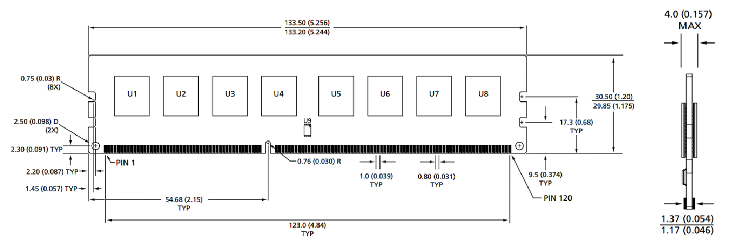
מידות מודול
נוף קדמי

נוף קדמי

הערות:
1. כל הממדים נמצאים במילימטרים (סנטימטרים); מקסימום/דקה או טיפוסית (טיפוס) במקום שצוין.
2. סובלנות בכל הממדים ± 0.15 מ"מ אלא אם כן צוין אחרת.
3. התרשים הממדי מיועד להתייחסות בלבד.
קטגוריות מוצרים : אביזרי מודול חכם תעשייתי


הצהרת פרטיות: הפרטיות שלך חשובה לנו מאוד. החברה שלנו מבטיחה לא לחשוף את המידע האישי שלך לכל אקסני עם ההרשאות המפורשות שלך.

מלא מידע נוסף כך שיוכל ליצור איתך קשר מהר יותר
הצהרת פרטיות: הפרטיות שלך חשובה לנו מאוד. החברה שלנו מבטיחה לא לחשוף את המידע האישי שלך לכל אקסני עם ההרשאות המפורשות שלך.